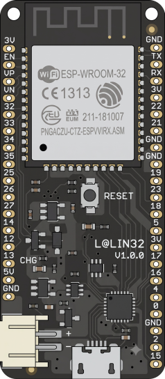
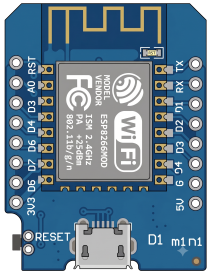
Connect an ESP32 or ESP8266 to Virtuino Cloud. This page walks through MQTT first — instant control, our recommended default — with HTTP right below it for battery devices that just report a reading. No sensor and no wiring needed either way.
The whole journey in 3 minutes — from empty account to a dashboard that turns your board's LED on and off.
Use the Sign In button at the top of this page, or create a free account if you don't have one yet.
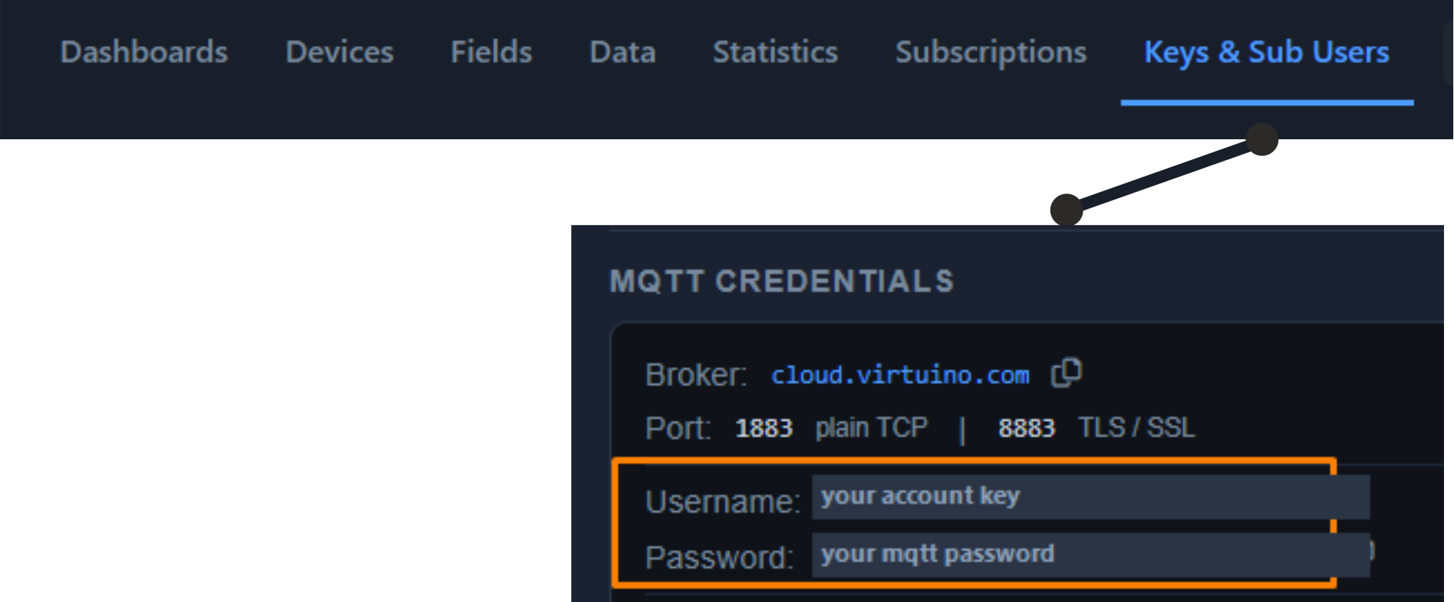
In the console open Keys & Sub Users. You need the username (your account key) and the MQTT password. The broker address and ports are shown there too.
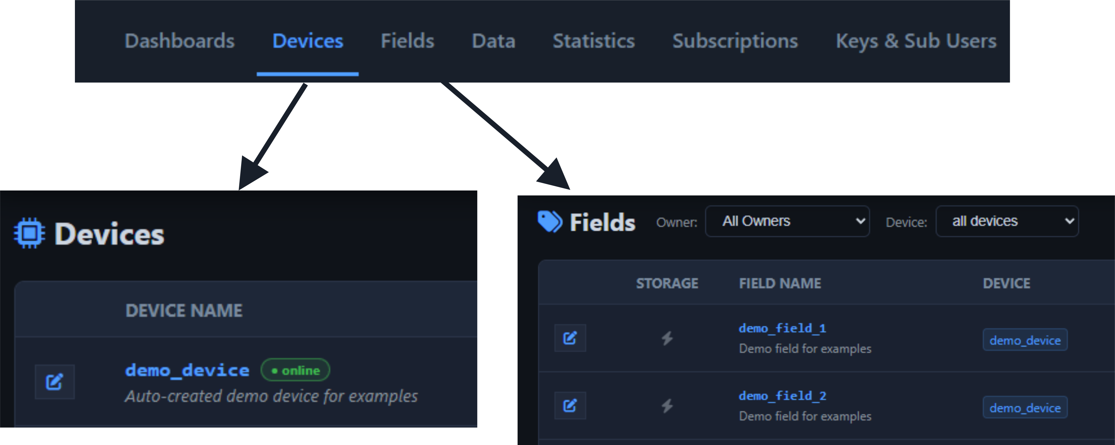
Two fields were created automatically when you registered:
demo_device/demo_field_1 and demo_device/demo_field_2.
Each name is the MQTT topic itself — the / only keeps related fields
together; you can name your own fields however you like. You can see them under
Fields.
The complete sketch. It publishes a made-up value to demo_field_1 every
3 seconds and listens on demo_field_2 to switch the built-in LED.
#if defined(ESP32)
  #include <WiFi.h>
  #include <WiFiClientSecure.h>
  WiFiClientSecure net;
#else
  #include <ESP8266WiFi.h>
  #include <WiFiClientSecureBearSSL.h>
  BearSSL::WiFiClientSecure net;
#endif
#include <PubSubClient.h>        // install "PubSubClient" by Nick O'Leary

#ifndef LED_BUILTIN
  #define LED_BUILTIN 2          // some ESP32 boards don't define it
#endif

const char* SSID      = "YOUR_WIFI_SSID";
const char* PASSWORD  = "YOUR_WIFI_PASSWORD";
const char* ACCOUNT   = "YOUR_ACCOUNT_KEY";      // MQTT username: your Sub-account Key - Console → Keys & Sub Users
const char* MQTT_PASS = "YOUR_MQTT_PASSWORD";

// The field names, exactly as in Console → Fields. No account key, no in/out —
// the broker knows your account from the login, and PUBLISH always means "to the cloud".
const char* pubTopic = "demo_device/demo_field_1";   // device → cloud
const char* subTopic = "demo_device/demo_field_2";   // cloud → device

PubSubClient mqtt(net);

void onMessage(char* topic, byte* payload, unsigned int len) {
    String msg;
    for (unsigned int i = 0; i < len; i++) msg += (char)payload[i];
    bool on = msg.toFloat() > 0.5;
#if defined(ESP8266)
    digitalWrite(LED_BUILTIN, on ? LOW : HIGH);   // ESP8266 LED is inverted
#else
    digitalWrite(LED_BUILTIN, on ? HIGH : LOW);
#endif
    Serial.println("demo_field_2 = " + msg);
}

void setup() {
    Serial.begin(115200);
    pinMode(LED_BUILTIN, OUTPUT);
    WiFi.begin(SSID, PASSWORD);
    while (WiFi.status() != WL_CONNECTED) { delay(500); Serial.print("."); }
    Serial.println("\nWiFi connected");

    net.setInsecure();                             // skip certificate check
    mqtt.setServer("cloud.virtuino.com", 8883);    // TLS
    mqtt.setCallback(onMessage);
}

void loop() {
    if (!mqtt.connected()) {
        // Client ID: any name, unique among your boards — the chip ID keeps it unique.
        // It is the name this board shows in My Virtuino World.
#if defined(ESP8266)
        String clientId = "demo-board-" + String(ESP.getChipId(), HEX);
#else
        String clientId = "demo-board-" + String((uint32_t)ESP.getEfuseMac(), HEX);
#endif
        if (mqtt.connect(clientId.c_str(), ACCOUNT, MQTT_PASS)) mqtt.subscribe(subTopic);
        else { Serial.println("MQTT failed, retrying..."); delay(2000); return; }
    }
    mqtt.loop();

    static unsigned long last = 0;
    if (millis() - last > 3000) {
        last = millis();
        float sensor_value = 25 + random(-5,+5);
        mqtt.publish(pubTopic, String(sensor_value).c_str());
    }
}
Replace the four placeholders at the top of the sketch with your own values.
const char* SSID      = "YOUR_WIFI_SSID";
const char* PASSWORD  = "YOUR_WIFI_PASSWORD";
const char* ACCOUNT   = "YOUR_ACCOUNT_KEY";
const char* MQTT_PASS = "YOUR_MQTT_PASSWORD";
In the Arduino IDE open Sketch → Include Library → Manage Libraries, search for PubSubClient by Nick O'Leary and install it. Then choose your ESP32 or ESP8266 board and the correct serial port, and press Upload.
Open the Serial Monitor at 115200 baud. Once WiFi and MQTT connect, the board starts publishing silently every 3 seconds.
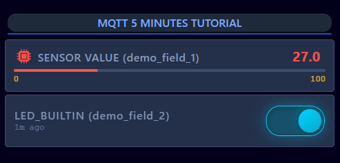
Create a dashboard and add two widgets: a value or level widget bound to
demo_field_1, and a switch bound to
demo_field_2. The value updates every 3 seconds, and the switch turns the
board's LED on and off instantly.
The same walkthrough on video, from an empty account to a working dashboard.

Use the Sign In button at the top of this page, or create a free account if you don't have one yet.
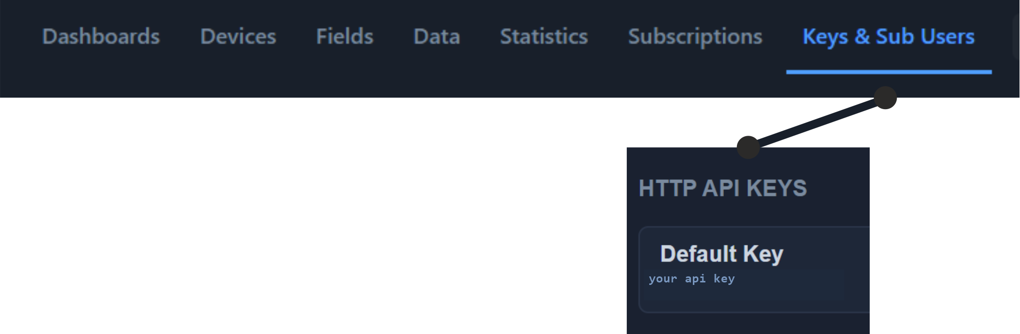
In the console open Keys & Sub Users and copy your Default Key from the HTTP API Keys panel.
The field demo_device/demo_field_1 was created automatically when you
registered. Its name is the topic you send to. You can see it under
Fields.
This is the complete sketch. It makes up a value around 25 and sends it every 3 seconds, so you can see data arriving before wiring any sensor.
#if defined(ESP32)
  #include <WiFi.h>          // ESP32
#else
  #include <ESP8266WiFi.h>   // ESP8266
#endif
#include <VirtuinoCloud.h>

const char* SSID     = "YOUR_WIFI_SSID";
const char* PASSWORD = "YOUR_WIFI_PASSWORD";
const char* API_KEY  = "YOUR_API_KEY";    // Console → Keys & Sub Users

VirtuinoCloud cloud(API_KEY);

void setup() {
    Serial.begin(115200);
    WiFi.begin(SSID, PASSWORD);
    while (WiFi.status() != WL_CONNECTED) { delay(500); Serial.print("."); }
    Serial.println("\nWiFi connected");
}

void loop() {
    float sensor_value = 25 + random(-5,+5);   // replace with a real sensor read

    // The field's full name, exactly as in Console → Fields (VirtuinoCloud 1.1.0 or newer)
    bool ok = cloud.write("demo_device/demo_field_1", sensor_value);
    Serial.println(ok ? "Uploaded" : "Upload failed — check WiFi and API key");
    delay(3000);   // upload every 3 seconds
}
#include <WiFiNINA.h> // Uno WiFi Rev2, MKR WiFi 1010, Nano 33 IoT, Nano RP2040
#include <VirtuinoCloud.h> // also install ArduinoHttpClient from Library Manager
const char* SSID     = "YOUR_WIFI_SSID";
const char* PASSWORD = "YOUR_WIFI_PASSWORD";
const char* API_KEY  = "YOUR_API_KEY";
VirtuinoCloud cloud(API_KEY);
void setup() {
Serial.begin(115200);
WiFi.begin(SSID, PASSWORD);
while (WiFi.status() != WL_CONNECTED) { delay(500); Serial.print("."); }
Serial.println("\nWiFi connected");
}
void loop() {
float sensor_value = 25 + random(-5,+5); // replace with a real sensor read
// The field's full name, exactly as in Console → Fields (VirtuinoCloud 1.1.0 or newer)
bool ok = cloud.write("demo_device/demo_field_1", sensor_value);
Serial.println(ok ? "Uploaded" : "Failed");
delay(3000);
}Replace the three placeholders at the top of the sketch with your own values.
const char* SSID = "YOUR_WIFI_SSID"; const char* PASSWORD = "YOUR_WIFI_PASSWORD"; const char* API_KEY = "YOUR_API_KEY";
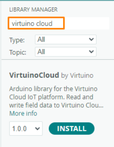
In the Arduino IDE open Sketch → Include Library → Manage Libraries, search for VirtuinoCloud and click Install. Install ArduinoJson the same way.
Choose the ESP32 or ESP8266 board and the correct
serial port, then press Upload. Open the Serial Monitor at
115200 baud — you should see Uploaded every 3 seconds.
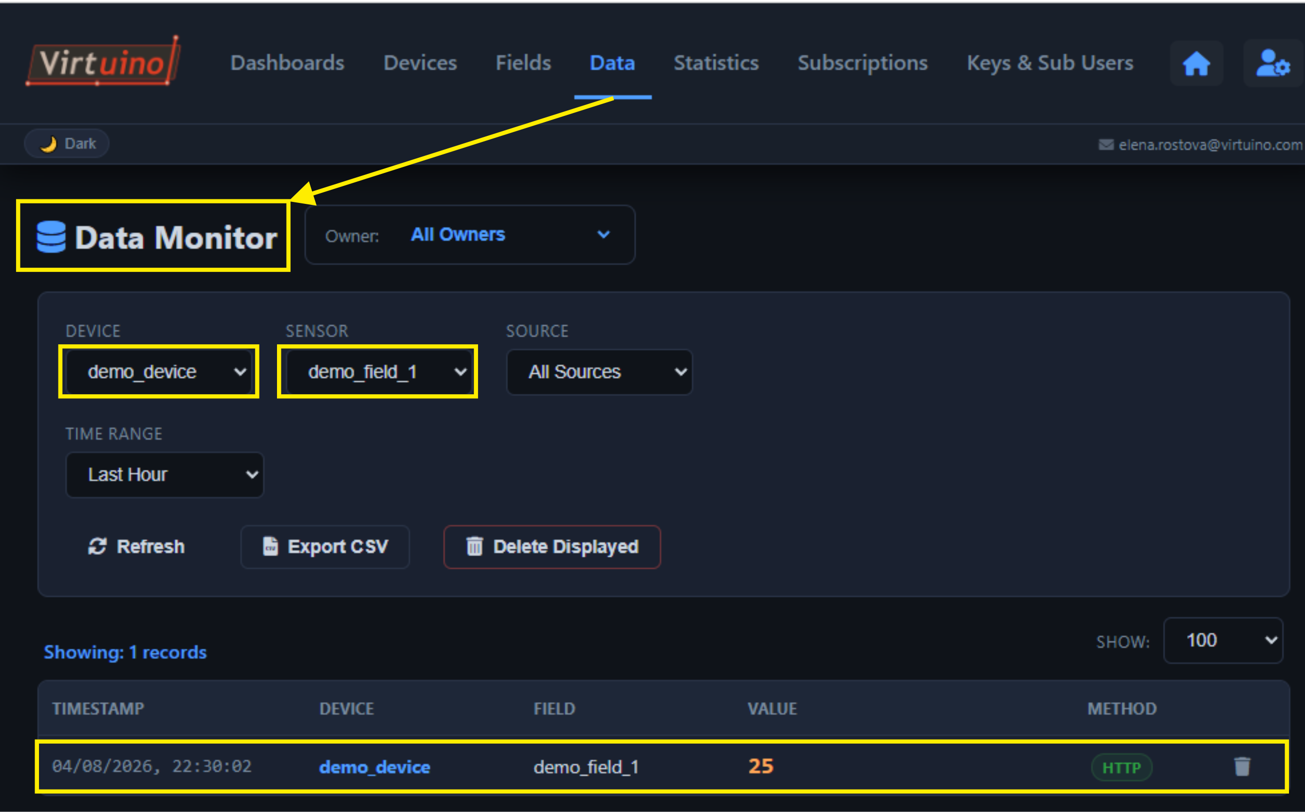
Open the console and go to Data → Data Monitor.
Select demo_device and demo_field_1 and your values appear.
Short version: HTTP to measure things, MQTT to control things. You are not locked in — the same device, fields and dashboards work with either.
The device sends a reading whenever it wants, then hangs up. Like posting a letter.
Advantages
Trade-offs
The device stays connected and messages fly both ways instantly. Like an open phone line.
Advantages
Trade-offs